
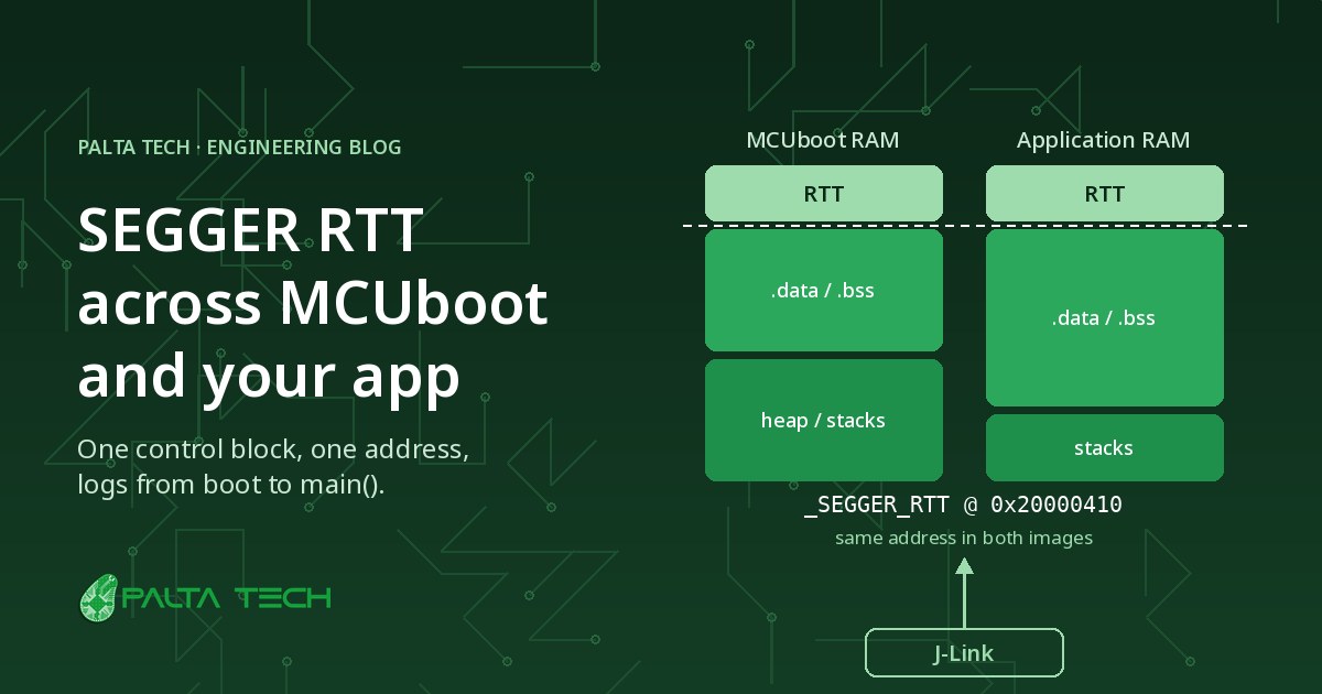
SEGGER RTT is the fastest way to get logs out of a Cortex-M over a J-Link, with no UART and almost no CPU cost. It works great with a single firmware image. Add MCUboot in front of your application, though, and the logs often stop the moment the bootloader jumps to your app. The fix is to place the RTT ring buffers at exactly the same RAM address in both images.
By the end of this article, you'll understand:
- How the RTT control block works and how J-Link locates it
- Why a bootloader plus application breaks RTT out of the box
- How to pin RTT to a fixed RAM address in both Zephyr images
- How to verify the layout and connect J-Link to the right place
How RTT Works
Real Time Transfer (RTT) moves data between the target and the host through plain RAM. The firmware writes log bytes into a ring buffer, and the J-Link reads them in the background over SWD while the core keeps running. No peripheral, no pins and no interrupts are involved, which is why RTT can log from inside an ISR without changing the timing much.
The Control Block
Everything starts at one structure in RAM, _SEGGER_RTT, the control block. It holds:
- A 16-byte ID string,
"SEGGER RTT", that marks where the block lives. - The number of up (target → host) and down (host → target) channels.
- For each channel: a name, a pointer to its ring buffer, its size, and the read and write offsets.
The ring buffers themselves (_acUpBuffer and _acDownBuffer for channel 0) are
separate arrays that the control block points to.
How J-Link Finds It
The host doesn't know where the linker put _SEGGER_RTT. By default, J-Link scans the
target's RAM for the "SEGGER RTT" ID string, remembers that address, and from then on only
polls the read and write offsets there. You can skip the scan by giving J-Link the address yourself, as
we'll see later. Either way, J-Link expects the control block to stay at one address.
The Problem With Two Images
With MCUboot, two independent Zephyr images run one after the other on the same RAM. MCUboot is linked
on its own, and so is your application, so each one has its own _SEGGER_RTT wherever its
linker happened to put it.
Symptoms
- You see the MCUboot banner in RTT Viewer, then nothing from the application.
- You attach after boot and get either silence or a few lines of garbage.
- Logs only show up after you disconnect and reconnect the RTT session.
- It works on one build and breaks on the next, because a new variable moved
.bssaround.
Root Cause
J-Link found MCUboot's control block, say at 0x20001a40. MCUboot then jumps to the
application, whose control block sits at 0x20003c18. J-Link keeps polling
0x20001a40, which is now part of the application's stacks or variables. Worse, the old
"SEGGER RTT" ID string may still be in RAM where MCUboot left it, so even a fresh scan can
lock onto the stale copy instead of the live one.
Key idea: if both images agree on where the control block and its buffers live, J-Link never has to look again. To the probe, the bootloader and the application look like a single program writing into the same ring buffer.
One Address for Both Images
Zephyr 4.0 and later include everything you need, and recent nRF Connect SDK releases carry the same options. The idea has three parts: give RTT its own linker section, put that section first in RAM, and stop the application from re-initializing what MCUboot already set up.
A Dedicated RTT Section at RAM Start
With CONFIG_SEGGER_RTT_SECTION_CUSTOM=y, the SEGGER module places the control block and both
ring buffers into a section called .rtt_buff_data. Zephyr's build adds this linker snippet
with a sort key of aaa, so it lands at the very beginning of the RAM region, before
.data and .bss:
SECTION_DATA_PROLOGUE(_RTT_SECTION_NAME,(NOLOAD),)
{
__rtt_buff_data_start = .;
*(CONFIG_SEGGER_RTT_SECTION_CUSTOM_NAME)
__rtt_buff_data_end = ALIGN(4);
} GROUP_DATA_LINK_IN(RAMABLE_REGION, RAMABLE_REGION)
Two details matter here:
- Same start, same contents, same address. MCUboot and the application share the same RAM base. When the section comes first and holds the same objects with the same sizes, every symbol in it ends up at the same address in both ELF files.
-
NOLOAD. The section isn't part of.bss, so the application's startup code doesn't zero it. Whatever MCUboot wrote there survives the jump.
Configuring MCUboot and the Application
Set the same RTT options in both images. With sysbuild, MCUboot's extra configuration
goes in sysbuild/mcuboot.conf next to your application:
CONFIG_USE_SEGGER_RTT=y
CONFIG_SEGGER_RTT_SECTION_CUSTOM=y
CONFIG_SEGGER_RTT_BUFFER_SIZE_UP=1024

CONFIG_LOG=y
CONFIG_LOG_BACKEND_RTT=y
CONFIG_RTT_CONSOLE=y
CONFIG_UART_CONSOLE=nCONFIG_USE_SEGGER_RTT=y
CONFIG_SEGGER_RTT_SECTION_CUSTOM=y
CONFIG_SEGGER_RTT_BUFFER_SIZE_UP=1024
CONFIG_LOG=y
CONFIG_LOG_MODE_MINIMAL=y
CONFIG_LOG_BACKEND_RTT=y
CONFIG_RTT_CONSOLE=y
CONFIG_UART_CONSOLE=n
On recent Zephyr versions, SEGGER_RTT_SECTION_CUSTOM is already the default on Cortex-M.
We still set it explicitly. It documents the intent, and it keeps the two images in sync if a
default ever changes.
Don't Wipe the Bootloader's Control Block
The original SEGGER code clears and rebuilds the control block on every SEGGER_RTT_Init().
In the application, that would reset the read and write offsets while J-Link is still reading them.
Zephyr adds an init mode that checks the block first:
# Only (re)initialize if the "SEGGER RTT" ID is not already there
CONFIG_SEGGER_RTT_INIT_MODE_STRONG_CHECK=y
STRONG_CHECK is the default. With it, MCUboot builds the control block after a cold boot, and
the application finds a valid one and keeps writing into the same ring buffer. RTT Viewer just keeps
scrolling from the bootloader banner into your main().
Verifying the Layout
Don't trust the configuration on its own. Check the addresses in the two ELF files after every build.
Comparing Symbols
Shellfor elf in build/mcuboot/zephyr/zephyr.elf build/app/zephyr/zephyr.elf; do
echo "== $elf"
arm-none-eabi-nm -n "$elf" | grep -E '_SEGGER_RTT$|_acUpBuffer|_acDownBuffer|__rtt_buff_data'
doneHere is the output from one of our nRF52 products. Both images match symbol for symbol:
Output== build/mcuboot/zephyr/zephyr.elf
20000000 b _acDownBuffer
20000000 B __rtt_buff_data_start
20000010 b _acUpBuffer
20000410 B _SEGGER_RTT
200004b8 B __rtt_buff_data_end
== build/app/zephyr/zephyr.elf
20000000 b _acDownBuffer
20000000 B __rtt_buff_data_start
20000010 b _acUpBuffer
20000410 B _SEGGER_RTT
200004b8 B __rtt_buff_data_end
The 16-byte down buffer comes first, then the 1 KB up buffer, then the control block at
0x20000410.
It's worth scripting this check and failing the build if the two lists differ.
Pointing J-Link at the Block
Now that the address is fixed, give it to J-Link instead of relying on the RAM scan. That removes any chance of locking onto a stale ID string:
- J-Link RTT Viewer: under RTT Control Block, choose Address and enter
0x20000410. - J-Link Commander or GDB: run
exec SetRTTAddr 0x20000410(in GDB, prefix it withmonitor). - J-Link RTT Logger: pass
-RTTAddress 0x20000410on the command line.
JLinkRTTLogger -Device NRF52840_XXAA -If SWD -Speed 4000 \
  -RTTAddress 0x20000410 -RTTChannel 0 boot.log
Pitfalls We Hit
-
Mismatched buffer sizes. The application reuses the control block MCUboot built, and
that block stores MCUboot's buffer pointers and sizes. If the application is built with a bigger
CONFIG_SEGGER_RTT_BUFFER_SIZE_UPor a different number of channels, the layouts no longer line up. Keep everyCONFIG_SEGGER_RTT_*option identical in both images. -
Something else at the start of RAM. Any other snippet or region that claims the
beginning of RAM in only one image shifts the RTT section in that image. That's what the
nmcheck catches. -
Different RAM bases. On parts with several RAM regions, or on multi-core chips like
the nRF5340, make sure both images are linked against the same RAM node. If they can't be, the
SEGGER_RTT_SECTION_CUSTOM_DTS_REGIONoption places the section in a memory region that you reserve in devicetree instead. - Older Zephyr versions. Before Zephyr 4.0, only the default and DTCM placements existed, and there was no init mode. On those trees, either backport the linker snippet or upgrade. Moving the block by hand in only one image is how you end up debugging the debugger.
- Production builds. RTT is a development tool. Disable it in release builds and lock debug access. The fixed RAM address costs nothing, but an open SWD port does.
Conclusion
RTT and MCUboot work well together once both images agree on one thing: where the control block lives.
Put RTT in its own NOLOAD section at the start of RAM, use the same RTT settings in the
bootloader and the application, let the application reuse the block it inherits, and check the
addresses on every build. You get one unbroken log from reset to main(), which is exactly
what you need when a field update misbehaves at boot.